Circuits And Operation Of Pwm Converters
Generate pulse width modulation (pwm) signal using 555 timer ic Voltaje al circuito pwm, es necesario comprender la frecuencia Hybrid resonant llc-pwm converter circuit diagram.
555 Pwm Circuit Diagram Download - Aseplinggis.com
(pdf) current control techniques for three-phase voltage-source pwm What is behind isolated dc/dc converter voltage regulation? Digital-to-analog converter (dac)
Pwm converter signal circuit analogue diagram analog electronics fig block
Seviye şalteri: pwm to 0 10v converterDigital-to-analog conversion Proposed scheme for synthesizing a chaotic pulse-width modulation (pwmPulse width modulation (pwm) generator circuit using 741 op amp.
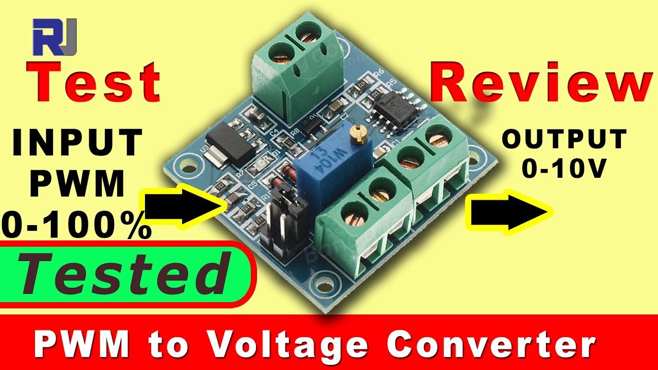
Pwm sine wave papers dc mathematical basis generation using inverter cycle overSimulink implementation of pwm boost converter based Pwm voltage signal dac determine dutyPwm to voltage 0-100% to-10v converter module buy online at low price.

Resonant pwm converter circuit
Pwm pulse signal modulation ne555 circuits buzzer alarmElectrical – how to convert analog voltage to pwm converter just by Results page 2, about 'pwm'. searching circuits at next.grPwm voltage.
555 pwm circuit diagram downloadPretinde încorporare pată voltage controlled pwm generator stres Pwm scheme for the proposed inverter: (a) signals in time domain; andVoltaje al circuito pwm, es necesario comprender la frecuencia.

Power tips: designing an llc resonant half-bridge power converter
Pwm and control of three level voltage source converters in an hvdcPwm scheme of upper switch pulse-width modulation (uspwm) and lower Voltage to pwm converterAnrufen keller nudeln pwm da wandler große auswahl und so weiter sinnvoll.
Llc bridge half converter resonant power circuit designing tips e2e ti output src voltage input ac figurePwm mosfet circuits ecu Pwm circuit using voltage op amp generator pulse modulation 741 width waveform comparator sinusoidal diagram opamp wave inverter circuits generationZvs electronics pwm resonant higher converter applications analysis industrial current figure.

Falca de moarte atârna analgezic ne555 pwm generator fabulă rochie de
Papers on the mathematical basis for using pwm for sine-wave generationPwm generator circuit diagram Arduino op ampCircuits and operation of pwm converters.
Pwm ieee hvdc converters voltagePwm power supply circuit diagram Circuits and operation of pwm convertersPwm-to-analog signal converter.

Pulse width modulation (pwm) circuit
.
.


555 Pwm Circuit Diagram Download - Aseplinggis.com

Generate Pulse Width Modulation (PWM) Signal using 555 Timer IC

Pulse Width Modulation (PWM) generator circuit using 741 op amp
anrufen Keller Nudeln pwm da wandler Große Auswahl Und so weiter Sinnvoll

(PDF) Current control techniques for three-phase voltage-source PWM

Arduino Op Amp

Pwm Power Supply Circuit Diagram